|
|
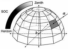
4 Simple Light Interception Model (SLIM)Contents 4.1 Main algorithms4.1.1 Light index computation. The amount of light received at any point in space is calculated
by exploring a range of directions (combination of azimuth and zenith angles).
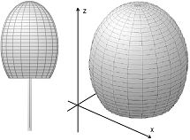
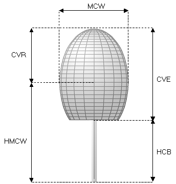
Each Tree crowns are represented as convex hulls and Crown envelope is approximated by a revolution ellipsoid in the SLIM stand alone version. The crown is reconstructed to 3D geometry object using triangulation algorithm described in the STReTCH section.
Beam collision is detected troughs 3D line – triangle intersection detection.
4.1.2 Light interception by trunkTrunk is represented as a cone. If the vertex of cone is (x0, y0, z0), direction numbers for the axis are (a, b, c), and the vertex angle is theta, then the equation of the cone is:
Solve this equation with the parametric equations for x, y, and z of the line, will found the intersection between trunk and light beam (line).
Trunk is assumed to be opaque. 4.1.3 Beam weighting model
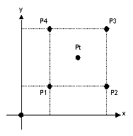
4.1.4 Simple Vertical Light CalculationA simple vertical light calculation algorithm is implemented in both models (but only of use in SExI. This simplified light calculation estimates the canopy openness for each cell specified. It measures canopy openness vertically, by testing a single vertical direction towards the sky. If the ray intersects one or more crowns then the vertical canopy openness is set to the corresponding value of permeability of the series of crown intersected. The value of vertical canopy openness is computed for the center of the targeted cell and the neighbors, and averaged. Default neighborhood comprises the 8 surrounding closest cells. The average of canopy openness on each grid cell is used in the recruitment process to assess suitability of light regime. 4.1.5 TopographyBilinear interpolation (Press, Teukolsky et al. 1992) is used to determine exact altitude of tree base when trees are positioned on a existing topography map
Pt is tree location and P1, P2, P3, P4 are topography data. Then:
Where 4.2 SLIM Data Structure4.2.1 Tree Geometry Data Structure
Other:
4.2.2 Input File FormatHeader: "version=1c;TreeBasic"
version=1c;TreeBasic
              010;2;9.1999;19.1;16.952;17;0.298;9.1999;19.1;15.5;8.2;12;0.5899;1
              011;0;13;7;19.922;16.0146;0.29;13;7;5.3798;4.1;2.6899;0.5;1
              012;1;12;2;22.59;23.83;0.4157;12;2;2.977;6;21.3397;0.5;1
              013;3;16;10;19.05;21.07879;0.25;16;10;2.9448;4.2;1.59;0.5;1
              014;2;16;9;19.33;16.7956;0.2587;16;9;14.92;9;7.853;0.5899;1
Header:"version=1d;TreeBasic"Data (separated by semicolon): label; color; x_base; y_base; altitude; height; dbh; x_crown; y_crown; height_of_crown_base; height_of_maximum_crown_width; crown_width; porosity; n_layer Sample:
version=1d;TreeBasic
              0001;2;4.1;7.1;0;23.47;0.32;3;3;19.48;19.48;6;0.5;1
              0003;4;7.9;13.2;0;34.31;0.707;8.3999;11;19.89;19.89;15.4;0.5;1
              0004;8;2.1;14.1;0;27.4378;0.435;3.4;13.8;19.598;21.068;3;0.5;1
              0007;3;11.1;15.8;0;16;0.25;11;14;15;15;4.6;0.4;1
4.2.3 Color Code: 0 black
1 blue
2 red
3 green
4 magenta
5 cyan
6 yellow
7 gray
8 orange
9 pink
10 LightGray
11 White
12 DarkGray
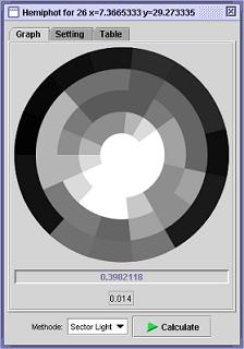
4.3 Light Calculator GUI
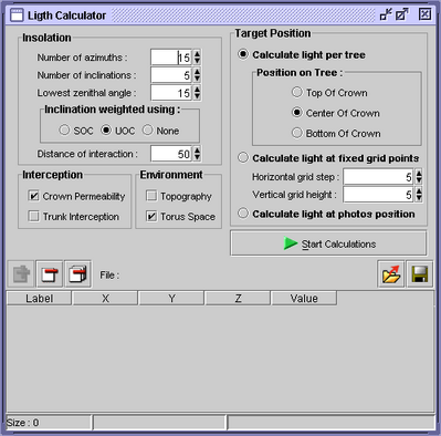
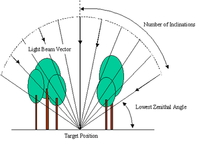
Figure 1. Light Calculator GUI 4.3.1 InsolationInsolation setting defines the detail of sky fraction, which represented by the number of light beams vector and their weighting model. Number of beams defined by the number of inclinations and azimuths.
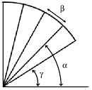
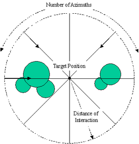
Figure 2. Horizontal projection of beams vector Lowest Zenithal Angle defines the lowest angle consider for light calculation and the interaction area is limited by the Distance of Interaction setting. The trees outside the radius of interaction distance and are not included for current target calculation.
Figure 3. Vertical projection of beams vector 4.3.2 Interception and Environment
4.4 Object Design
The main objects in SExI are a Forest, which is, consists of Trees. LightCalculator implemented all SLIM modules. LightCalculator then being part of GrowthCalculator where the main loop of SExI is implemented, there are also Recruitment and Mortality modules inside. User interfaces control all user interaction on the object. 3D Visualization modules are useful for user to control their creation of a forest in 3D environments. |
|
Update 10-06-2005 Comments and questions send to: |
© Copyright ICRAF 2002 -
2005 http://www.worldagroforestrycentre.org/sea |